
Project Structuring
This article presents the latest Renga 5.0 release and follows our course chosen in the second half of 2021 to improve the Renga functionality when working with drawings, namely: modernizing the Project Explorer; automating tools for drawing documentation generation and preparation; creating designer-specific schedules (by obtaining new data using formulas and additional quantities of model objects); optimizing performance when working with large amounts of graphic data; and maintaining compliance with Russian drafting standards. More details about all the 5.0 release new features are provided below.
All the features built into previous versions have been updated in the latest release, making the work of users more comfortable. This time the Project Explorer has been improved to group such project components as Drawings, Levels, Assemblies, Sections, Elevations, Schedules, and Tables.
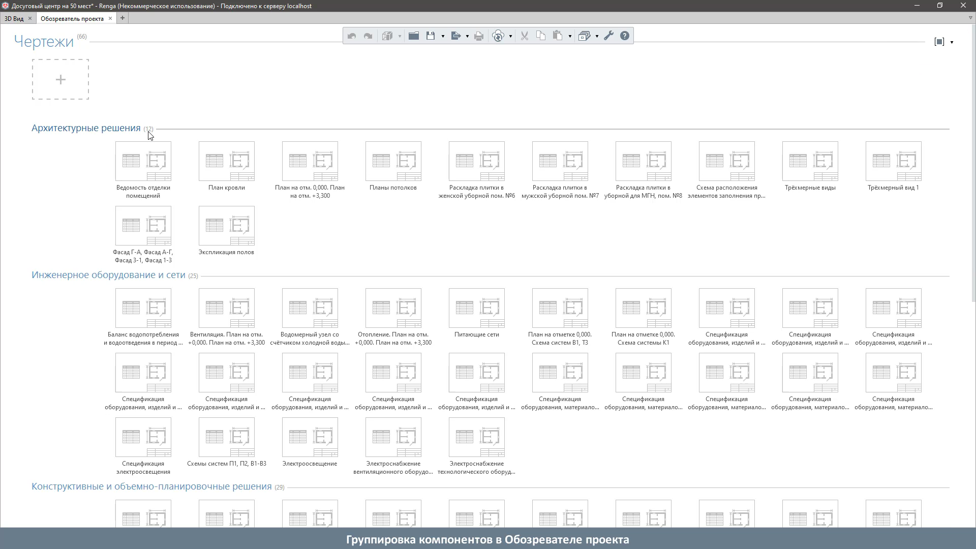
Now it will be easier for the user to navigate projects with a large number of drawings because the components can be grouped by name, section, developer's name, and other assignable properties.
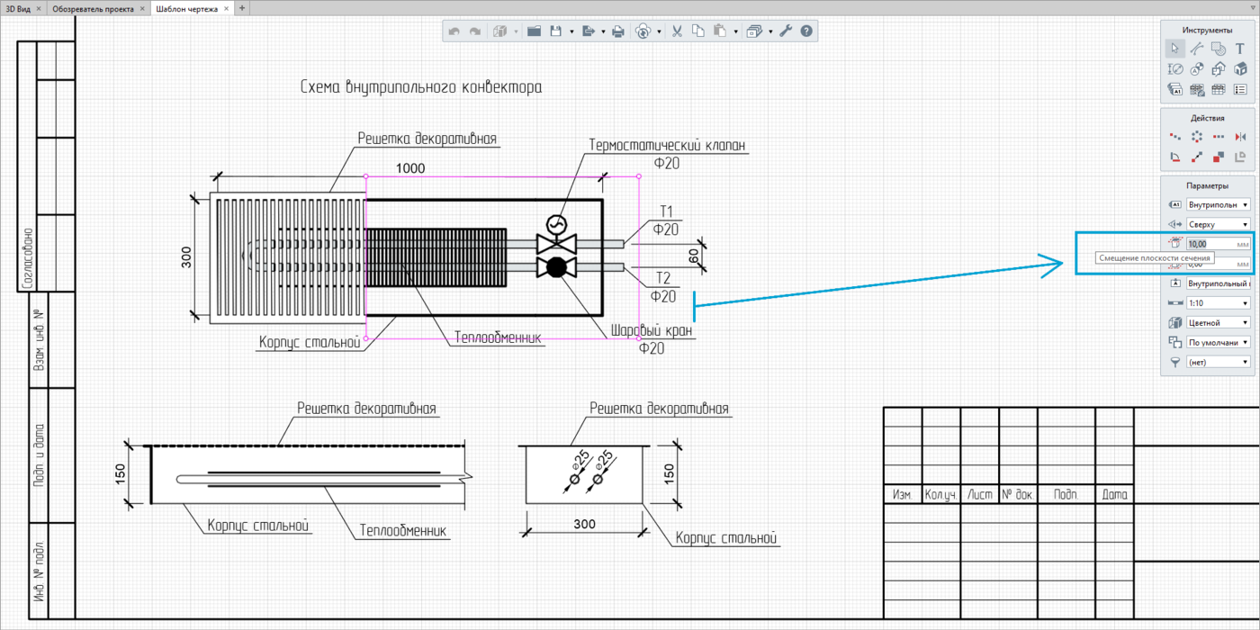
In addition to grouping, attention was paid to the detailing of model object drawings, the required level of which can be easily achieved by controlling the section plane and visibility depth of the Object in the drawing view. Previously, this feature was available only in general model views (plans, sections, elevations). Now MEP engineers, for example, can create equipment connection diagrams – thermal curtains, ventilation systems, radiators (in-floor convectors in particular), thereby displaying both the outside and inside equipment details.
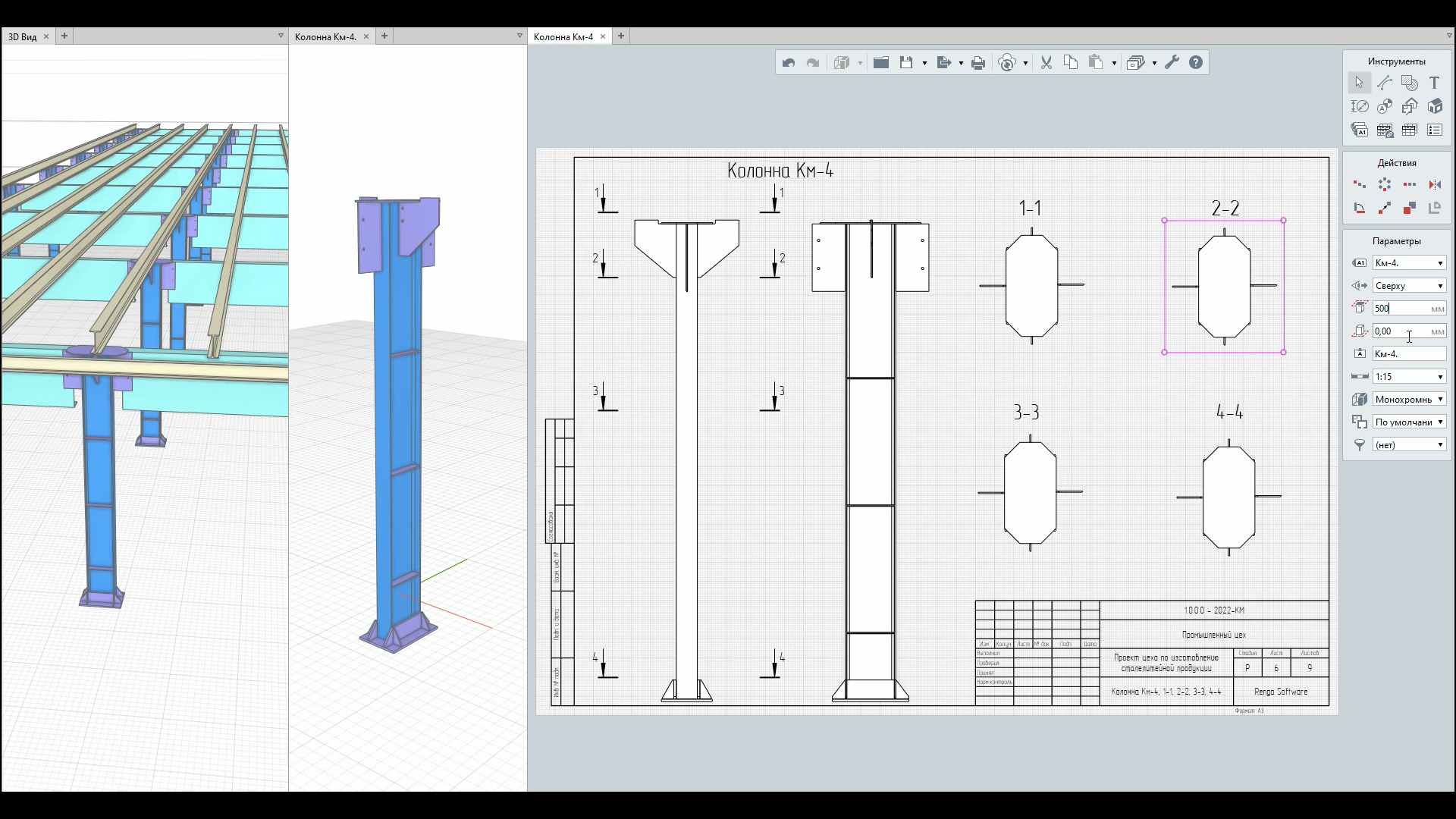
At the same time, structural designers can receive structural drawings with specific height sections.
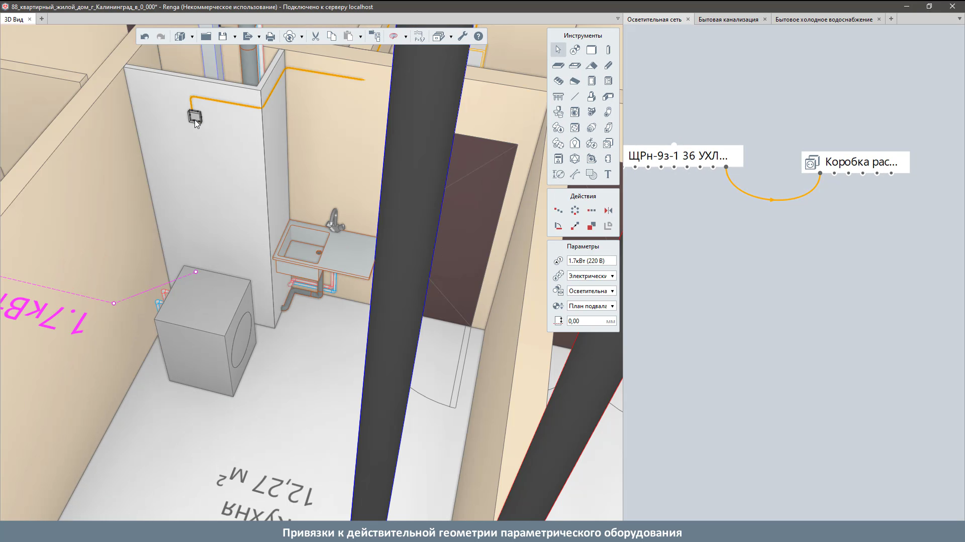
At the request of MEP and process engineers, Renga has been updated with parametric object snap points freely placed in the model view.
Object snaps are especially useful when, according to the design concepts, an engineer needs to designate a trace point in a specific equipment area – face, plane, vertex, etc. – and use it to connect the equipment to an additional engineering route. For example, this is helpful when working on the power supply for ventilation or boiler equipment, washing machine, dishwasher, etc.
In addition, the overall equipment cube, which could lead to difficulties in manually editing MEPs through trace points, has been removed. Now the object's geometry reflects the real equipment structure without phantom lines.
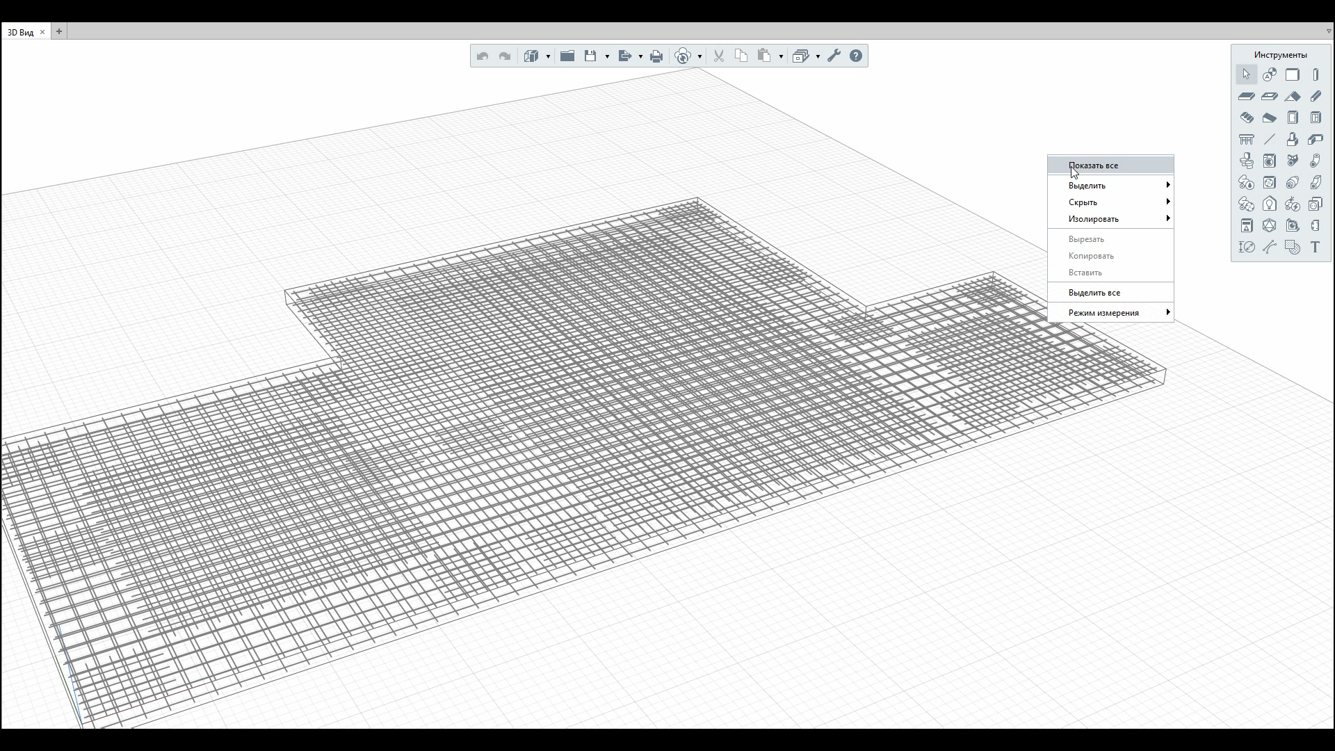
Our active users used to send us requests to implement the ability to use filters when creating an Assembly. No sooner said than done. This feature allows the designer to apply filters in the Assembly, namely: Select, Hide and Isolate objects to speed up the design of individual construction units. This option, for example, will be useful for a structural engineer when working on the reinforcement of RC structures.
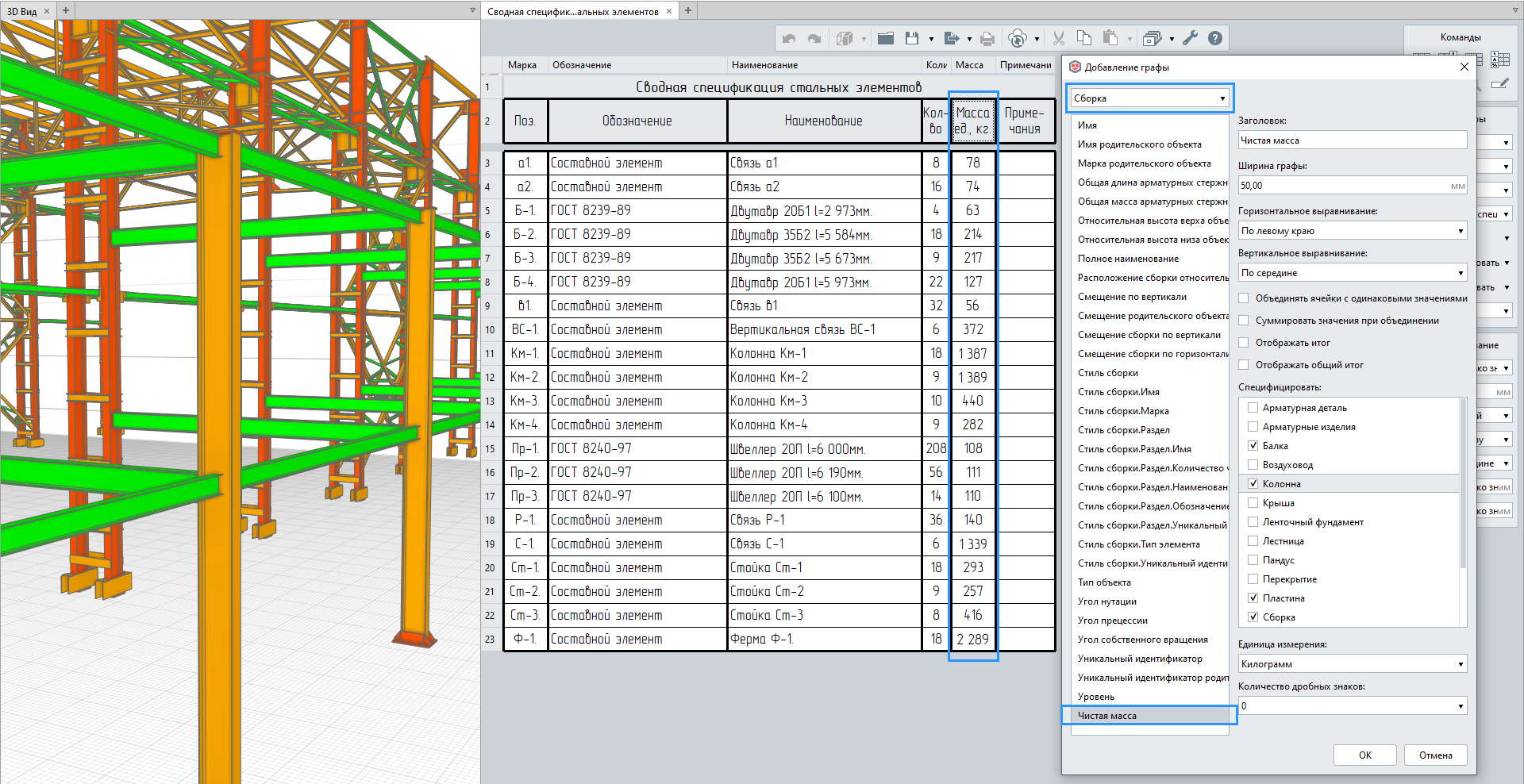
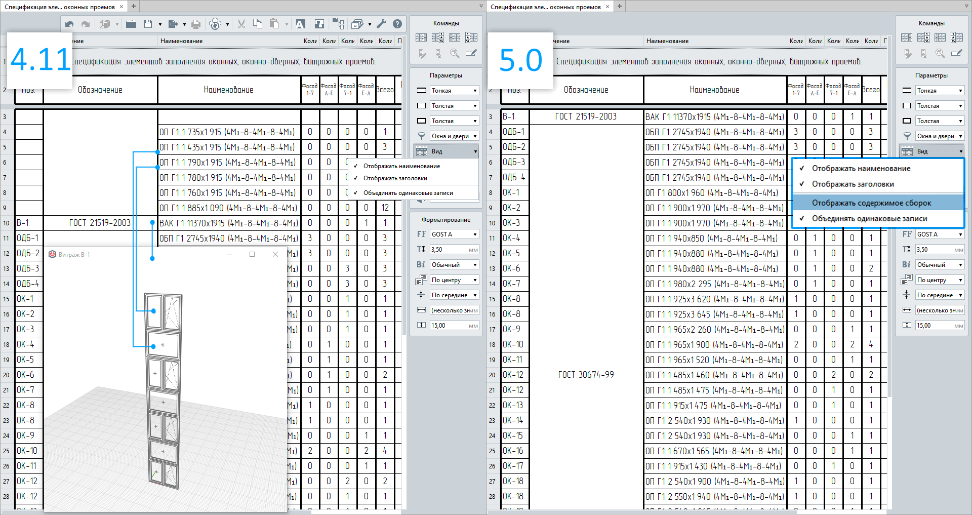
But there are even more innovations regarding Assemblies. "Display assembly contents" option has been added in Schedules and Legends. This option will be useful for both structural engineers and architects. It allows the assembly details to be either shown or hidden. For about half a year, this could only be done through filters. For instance, this feature allows creating schedules containing reinforcement details, reinforcement units (assembly-like), window opening schedules, including windows and curtain glass walls.

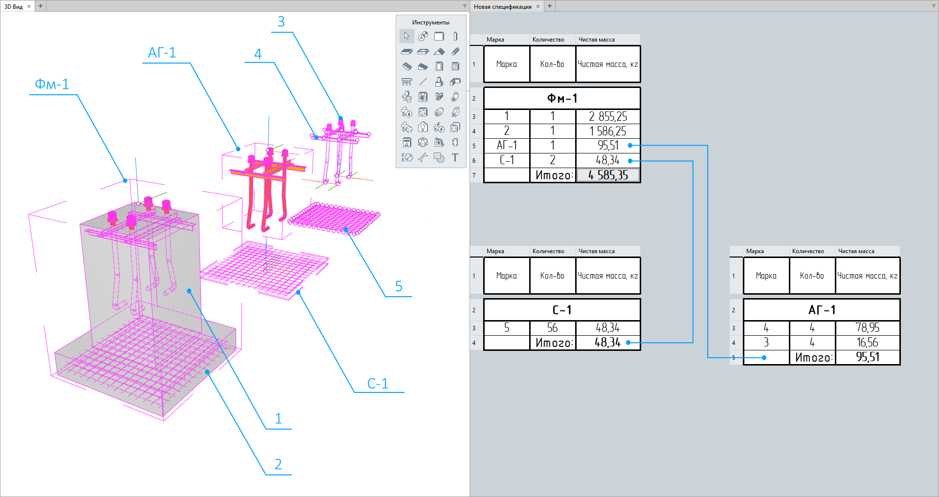
But that's not all. Now users can not only quickly set the display of assembly details in schedules but also automatically receive the net mass of the entire assembly. Namely, the summary of the net masses of its constituent objects, i.e., the way the designer modeled it (with all cuts, holes, and openings).
And since now the Assembly tool allows to add embedded and composite assemblies (see "Assembling Into a Single Unit"), this method of automated mass calculation becomes even more popular and will appeal to absolutely all designers, especially structural engineers who have been waiting for this feature.
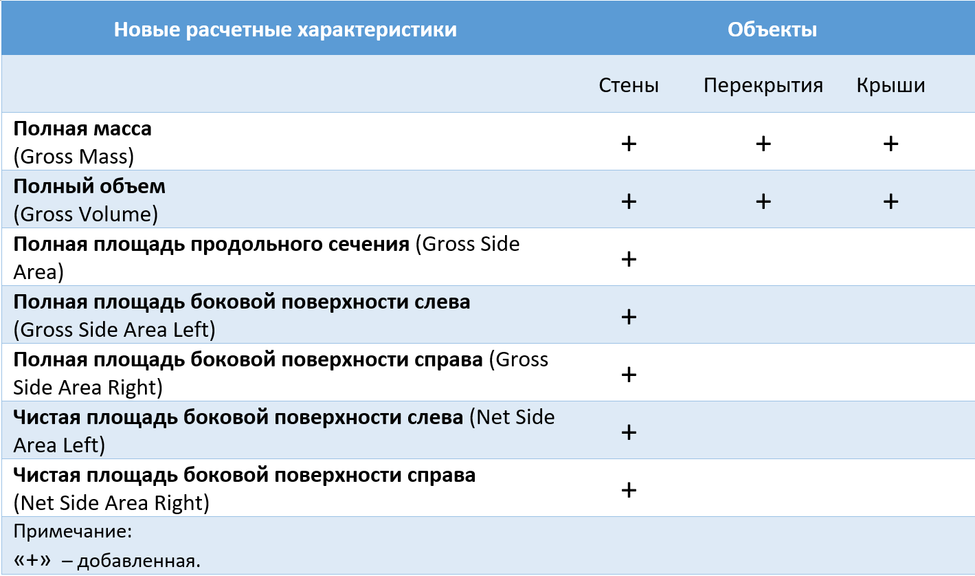
We continue adding new quantities to model objects. And each of the added characteristics is very important for designers. Walls, roofs, floors, and assemblies have acquired new quantities. To make the picture complete, they are listed in the table below.
Let's review the usefulness of each characteristic through examples.
• These characteristics will allow to find out the surface area excluding openings and various cuts that occur when the walls interact with other structural elements.
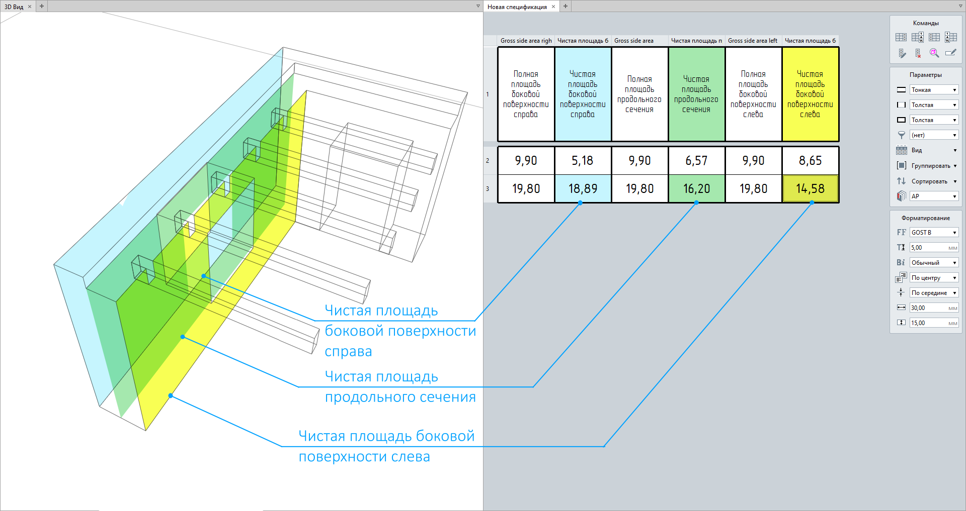
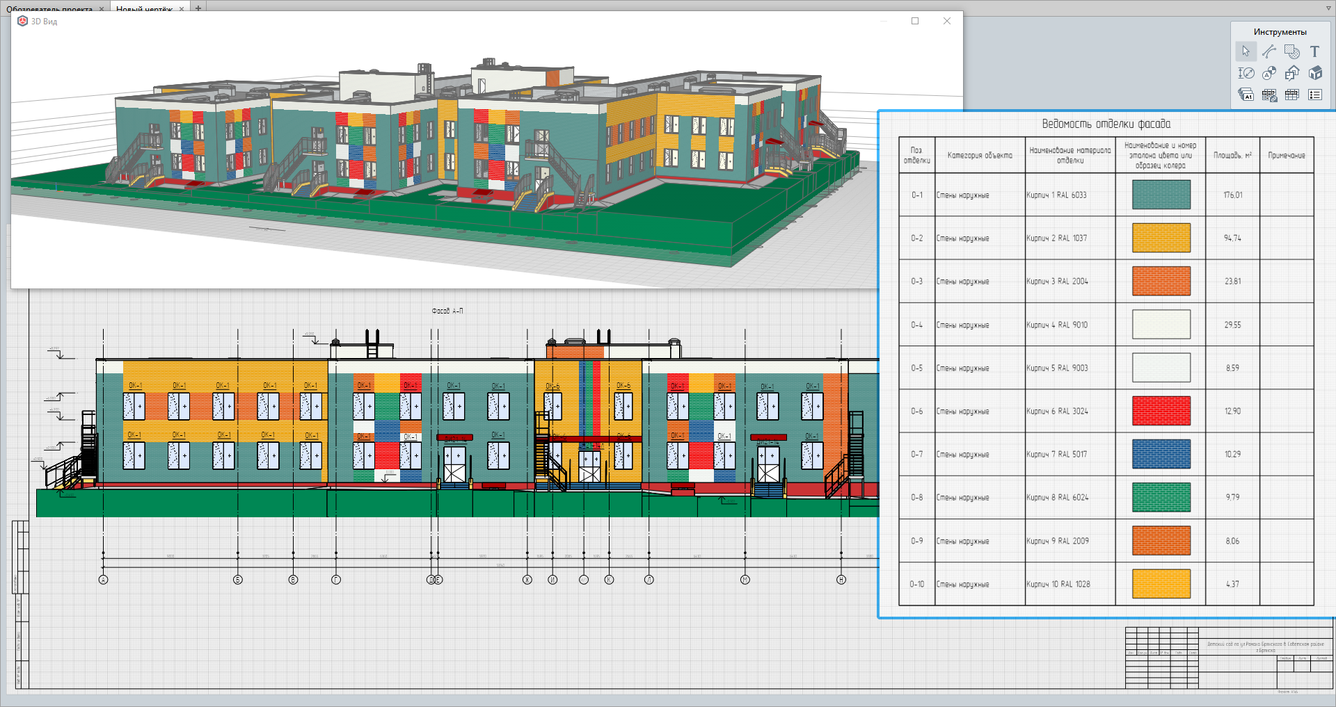
Due to this, the architect will be able to calculate, for example, the elevation finish area.
• Gross axial and right/left side areas will allow to find out the area excluding the existing openings, holes, or cuts. If openings and holes are made at the construction site, these characteristics will be needed to calculate the wall areas to be finished or coated with protective materials (waterproofing, thermal insulation).
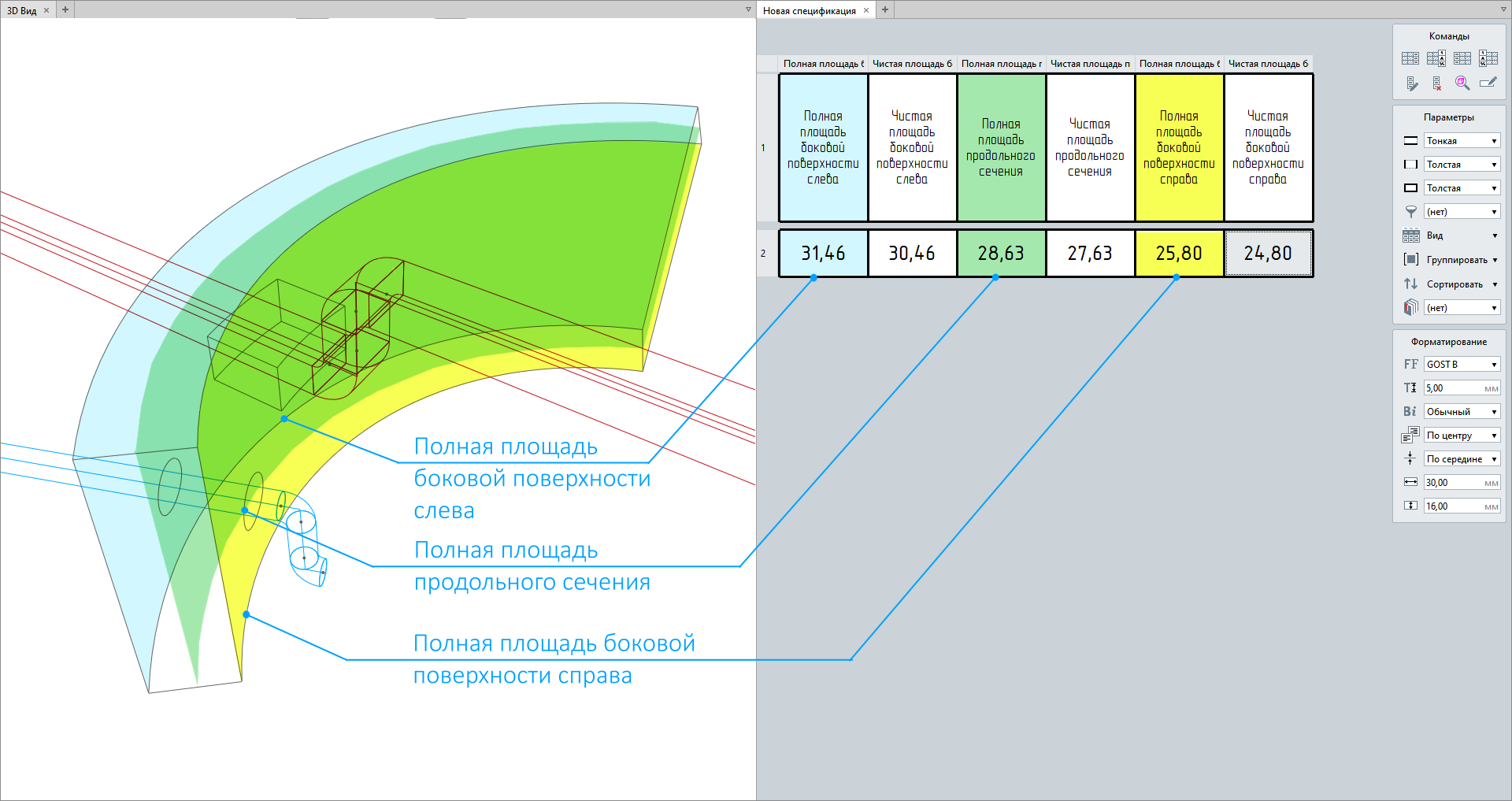
A key point when calculating overall characteristics is that the latter are calculated excluding wall joints, so the gross right side and left side areas of straight walls will be equal. But the difference between these characteristics will be clearly visible of arch-built walls.
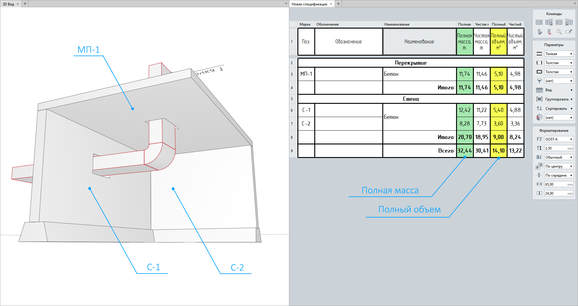
• The gross mass and volume of walls, floors, and roofs will also help to determine characteristics excluding cuts, interactions with other elements, and the holes in them. If to continue the analogy of making holes at the site, then the amount of material (e.g., concrete) is calculated with such holes excluded. And, to correctly calculate the concrete volume for floor or wall purposes, these characteristics will be essential to designers.
New quantities have also been added to the corresponding APIs and became available to third-party application developers.
We're constantly working on Renga optimization. And the latest release allows opening drawings of section views significantly faster. Compared to previous versions, the waiting time of placing views in a drawing has been reduced, and the editing of the section position in a model view is much faster.
However, depending on the visibility depth and rendering detail, these processes may take more or less time.
Another innovation also concerns the design speedup and the designer's comfort but in a different plane.
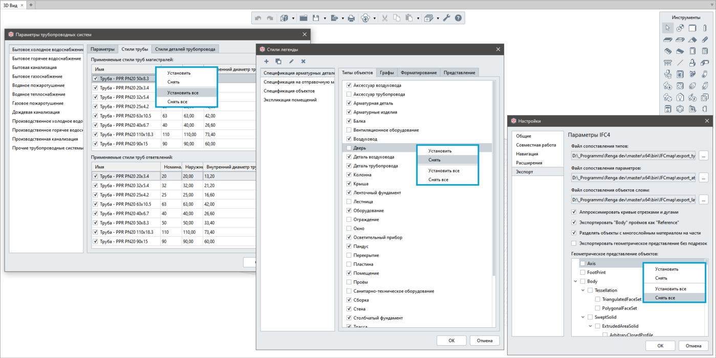
Now, with a new context menu, when you have to mark at once or, on the contrary, unmark all the necessary elements of the Display Styles, Legend Styles, Schedule Column, Common Schedule Column, Geometric Representation of Objects for IFC Export, and Parameters of Pipeline, Ventilation and Electrical Systems, the designer will no longer have to do it one at a time.
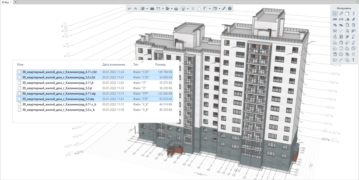
We have also optimized the export of files to various formats. This mainly applies to the C3D format, as well as JT, STP, and Parasolid.
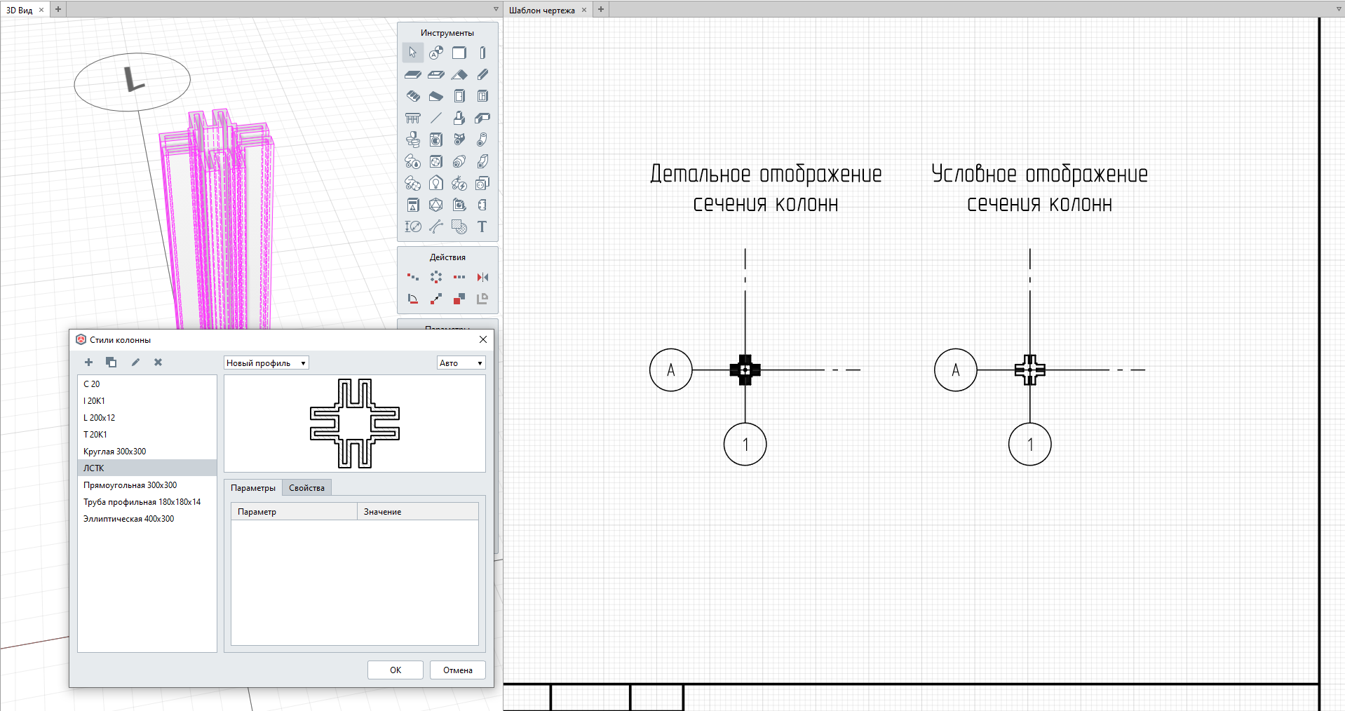
In terms of drawings, at the request of users, the way sections of columns and beams created in the Profile Editor were displayed has been changed. In previous versions, sections of columns and beams were sometimes difficult to read due to overlapping section lines. In the latest release, only the external section contour is indicated in section projections created with the help of the Profile Editor.
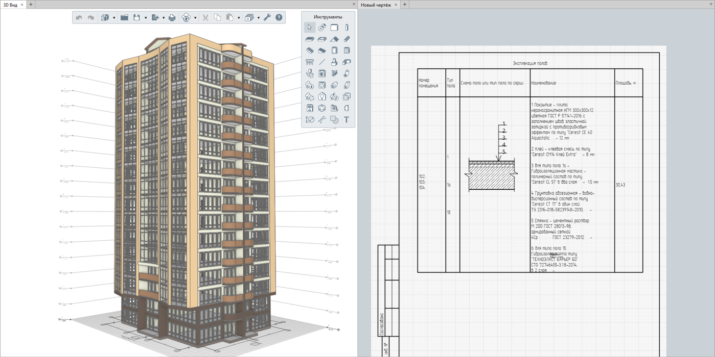
Besides, at the request of designers, the maximum possible line height in Tables, Legends, and Schedules has been increased from 150 to 300 mm. This will allow creating schedules with graphical data that require more vertical space per line, e.g., for flooring schedules.
In terms of project collaboration, the latest Renga release allows collaborating users to connect to the Renga Collaboration Server using an access key. This feature helps users restrict access to the Collaboration Server instance on the company level.
It is also worth noting that previously designers had difficulties reading the names in the Parameters of Pipeline Systems and Parameters of Ventilation Systems windows due to their incomplete display. The new release has no such problem, allowing to adjust the aspect ratio of these windows and see the full name of the selected material.
As it stands, this is major Renga release. In this regard, for technical reasons, we have to disable automatic conversion of Renga projects version 4.0 or older. This means that projects created in Renga versions older than 4.0 will now be opened in two stages:
• converting a project to 4.x version (opening and saving a project in 4.x version);
• opening a project in 5.x version.
But it shouldn't be a problem for you. If you need help with converting such projects, you can always contact the Technical Support Service.
If you haven't tried Renga yet, please download the trial version. Or, if you are already a commercial user, please visit the Download Center to get the latest version.
Posted by: Irina Bryleva and Evgeniy Kiryan, Renga Product Marketing Managers